
Ultrasonic technology intensification oil recovery and gas condensate

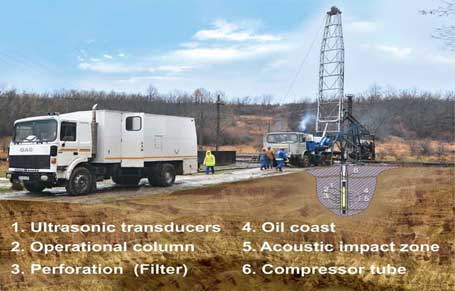
The geoacoustic complex (technique) for the intensification of oil recovery consists of the powerful ultrasonic generator and ultrasonic transducer , powered through a standard 3 core logging cable.
The whole equipment, realizing the acoustic stimulation technology, is in coordination with the regular equipments of geophysical parties which does not cause any difficulty in its adaptation by the regular geophysical personnel.
The acoustic stimulation technology consists in the processing of collector layers (in the open bore, filter interval or perforated holes) by powerful ultrasonic field aimed at the restoration of their filtering properties.
Processing is carried out point wise (with 0.5-1.0 interval) selectively based on the "inflow stimulation profile" principle.
Well and equipment preparation is practically the same as that for standard geophysical researches.
The integrity of the operational column and cement stone over it is ensured and the process of stimulation is technically and physiologically safe and environmentally sound .
Without exaggeration we can say that nowadays acoustic stimulation of oil wells is modern, hi-tech, absence of reagent geophysical method of operated and selective influence on a layer and bottomhole zone for an intensification of inflows and oil recovery increase, applicable in a wide range of geological-technological conditions, with rather long (till 2 years and more) and essential (often multiple) effect, besides is almost faultless for a layer and an oil well and is ecologically pure, and also is easily combined with other known methods of an intensification and increase of oil recovery.
This technology allows, without any damage to oil-bearing sand, to achieve effectively restoration of filtrational properties of productive layers at minimum time and material inputs.
Application ultrasonic and information technology in oil and gas engineering
|
The processing of operational and delivery wells for increase of their efficiency ( throttle response ) and increase oil recovery . |
|
||||
|
Processing of filters, oil well tubes, pumps and other equipment from preventing (maintenance prevention and liquidation) the paraffin formation and other asphalt-resinous paraffin deposits. |
|
||||
|
Processing of commercial sites and main pipelines, process vessels etc. with the objective of the change of rheological properties of oil and petroleum products (decrease in viscosity etc.) |
|
||||
|
|||||
|
Developing of software for numerical modeling of an oilfield. |
|
||||


Competitive advantages of complex approach to ultrasonic treatment
|
Technology Options |
Brief description |
|
Absence of Reagent |
No need for expensive chemicals (acids,solvents, surfactants, etc.) |
|
Selectivity |
Selectivity of influence on various phases of the multiphase environment and selectivity of extraction of useful components. |
|
Manageability |
Operative Controllability time and intensity of influence, speed of processes, etc. on the basis of a feedback. |
|
Indestructible |
Indestructible structures of environment and «renewability» influences with initial parameters. |
|
Manufacturability |
Machine less , Small no. of operations , an opportunity of automation, etc. |
|
Ease |
Flexibility, mobility and fine tuning of technology |
|
Combinability |
Possibility of simultaneous (parallel) influence on different phases, including combined with material methods. |
|
Environment |
" Flawless " (convertibility "after effect ") for the geological environment, small destructiveness to the environment, convenience of manufacturing. |
|
Cost |
Lower cost and labor intensive compared with all other methods and technologies. |
|
Reduction of production cost |
Numerical modeling allows to calculate set of variants of oil production. |
|
Increase of service life of equipment |
On the basis of virtual models of engines and pumps their exact selection is carried out |
|
Energy efficiency |
Selection of optimal operating modes of equipment |
|
Increasing of oil recovery from deposit |
The complex and consecutive approach to developing of a deposit on the basis of the presented technologies. |
The plan of organizational-technical actions on oil and gas deposits during ultrasonic stimulation.
1. Preparatory organizational-technical actions
The analysis of information given by the customer;
Selection of oil wells for acoustic stimulation, taking into account their technical-operational characteristics and dynamics of change of an output from the moment of putting them into operation.
Information should include:
- Well logging maps,
- Profile of inflow,
- Permeability of alternation,
- Technical and operational indicators of an oil well,
- Information about repair and technical operations for intensification of oil and gas production.
Development of plan of works on ultrasonic stimulation of oil well and its coordination with executors.
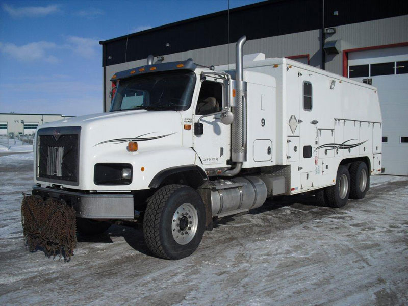
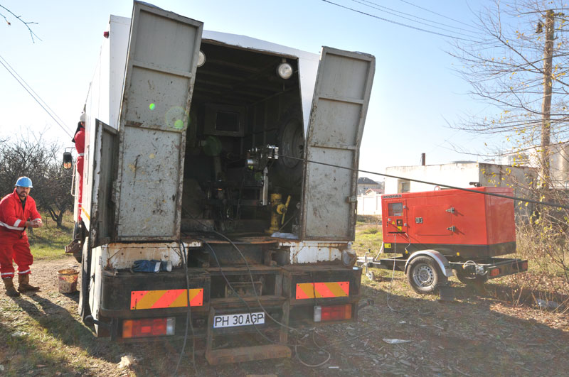
Geophysical equipment includes geophysical lift and the mobile geophysical laboratory , providing background thermometry, immersing binding, cabel-rope to a productive zone of layer.
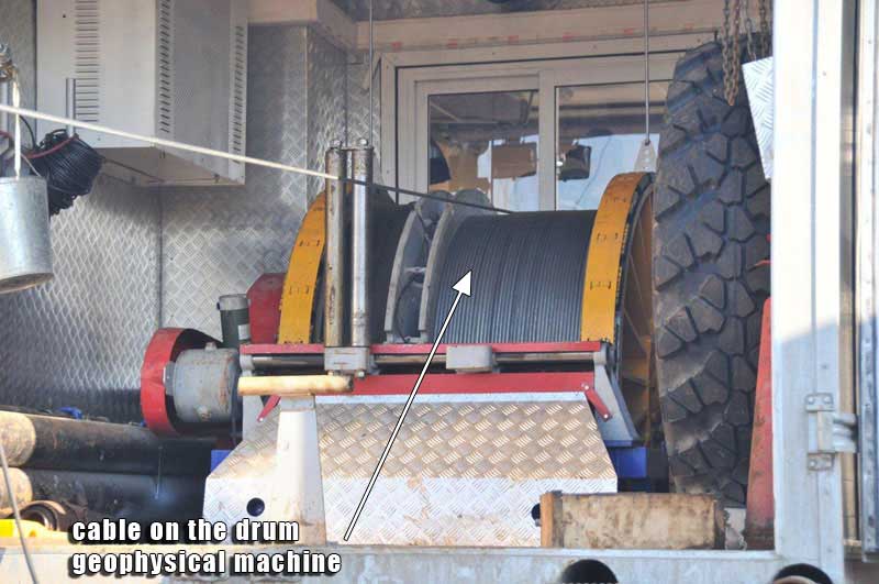
Preparation of the geophysical lift and cable - rope with a small geophysical head (diameter 38mm).
Parameters of cable KG-3:
- Running resistance of lead vein R-12-15 the Ohm/km,
- Length of a cable – 3000-5000 m.
Equipment of mobile geophysical laboratory by a network cable for a mains system of 3 phases, 380 V, 50 Hz, (with capacity of consumption to 15 kw), a typical three-phase plug and the automatic machine on the maximum current of 25 A
Preparation of measuring equipment for developing of preparatory and control checks of the equipment of technological system of ultrasonic influence and measurements of parameters of a cable line. Measuring equipment includes: the setting generator, an oscillograph, the alternating voltage voltmeter.
2. Spadework on the basis of geophysicists
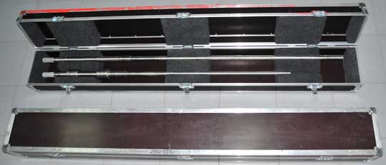
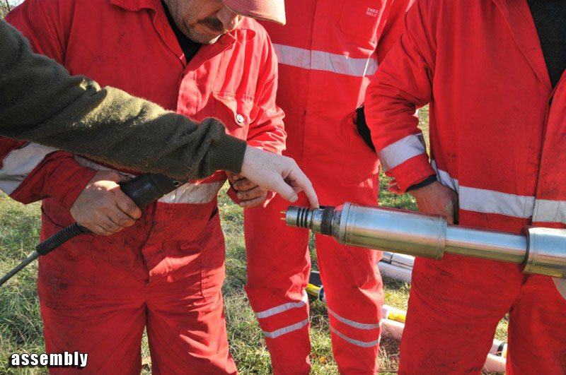
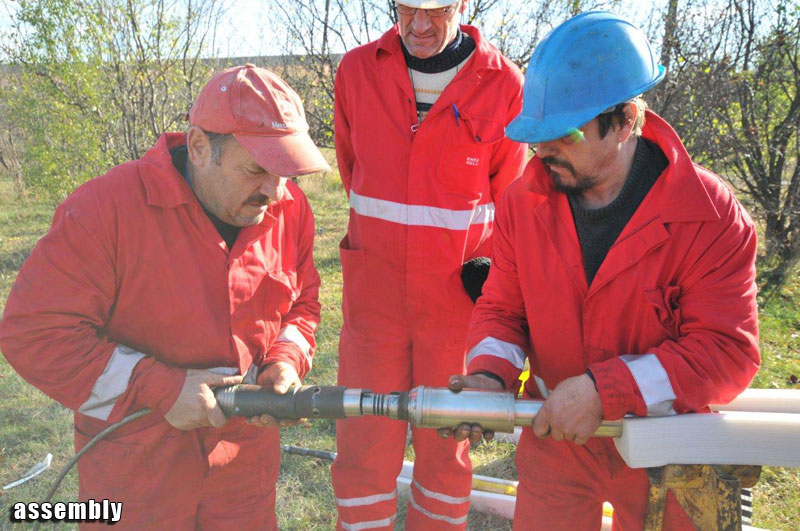
Delivery of the ultrasonic equipment on the geophysicists base. The typical structure of the equipment consists of one complete set of the land generator and two types of acoustic transducers. The total weight of the equipment with packing container is50-75 kg.
Check of functioning of the ultrasonic equipment according to the maintenance instruction, connecting equipment with equipment of geophysical laboratory and with a cable of the geophysical lift.
Measurement of coefficients of geophysical cable in a range of working frequencies. Check of limiting characteristics of a cable at work of the generator and an acoustic transducer through a cable on a loading equivalent.
Preparation of the ultrasonic equipment and the special geophysical equipment to leave for working on oil wells.
Specification of the scope of works on concrete oil wells,
- time of ultrasonic stimulation,
- modes of radiation,
- number of stations and their arrangement in a productive zone.
The coordination of works with the leading geologist and customer supplying services, setting time of the beginning and termination of ultrasonic stimulation.
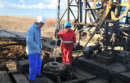
3. Spadework on oil wells
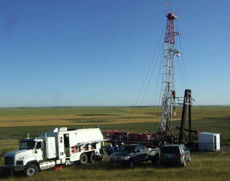
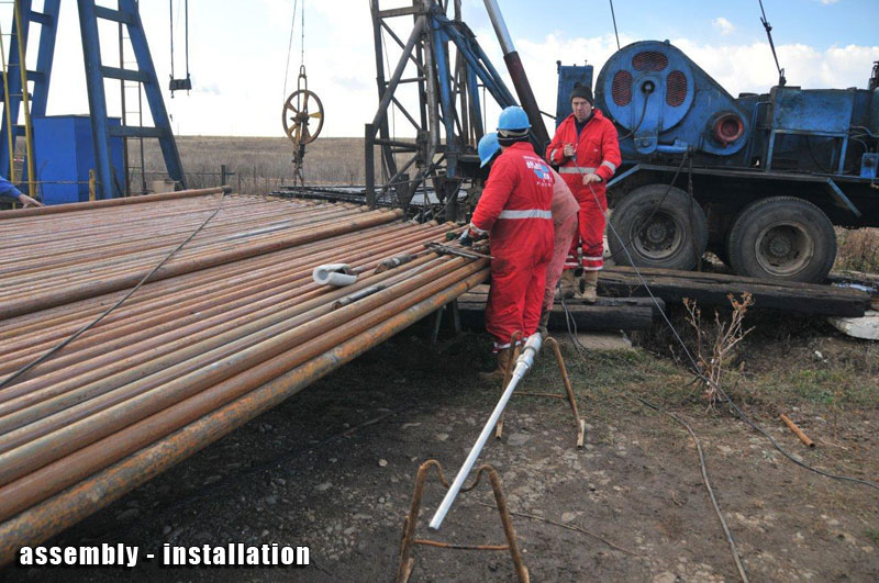
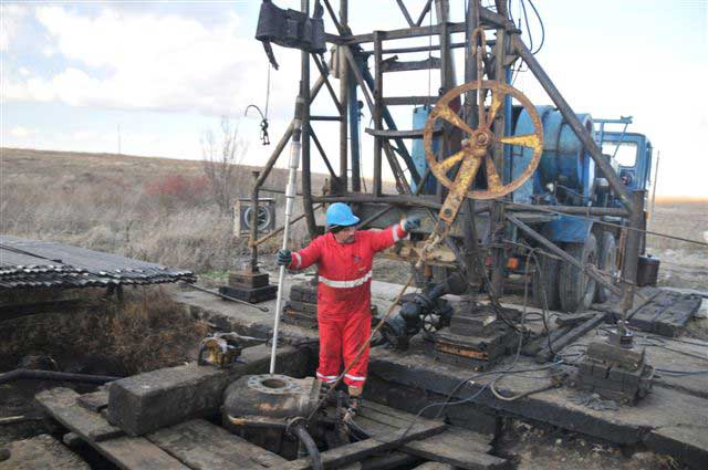
Delivery of geophysical equipment to a work place on an oil well.
Checking technical readiness of an oil well for ultrasonic stimulation, including possibilities for power supply, presence lifting equipment.
Installation of the geophysical lift and geophysical laboratory, land generator, technological system of ultrasonic stimulation and measuring equipment.
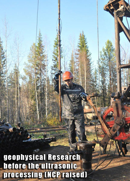
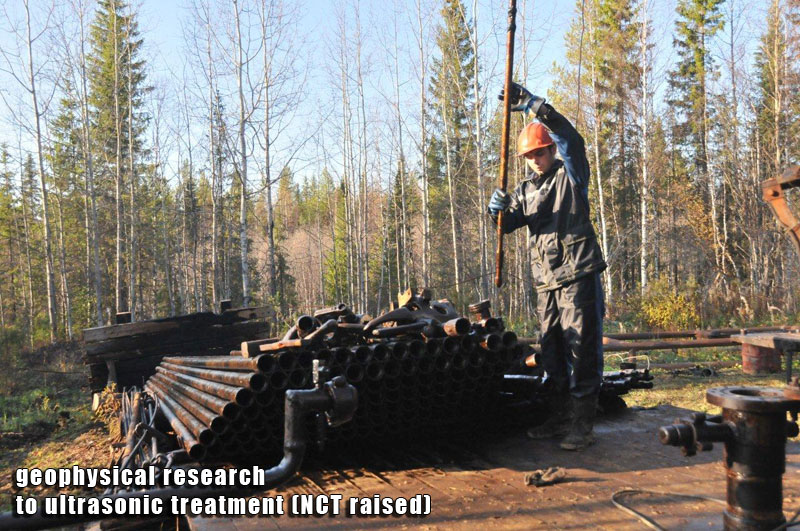
Carrying out of geophysical measurements before ultrasonic stimulation, including:
- Background thermometry of a productive zone,
- Connecting equipment to a contour of grounding and a lining of cable connections.
- Connecting a network cable;
- Controlling of voltage of a network of power supplies;
- Connecting an ultrasonic transducer to an output of a geophysical cable;
- Checking of resistance of isolation.
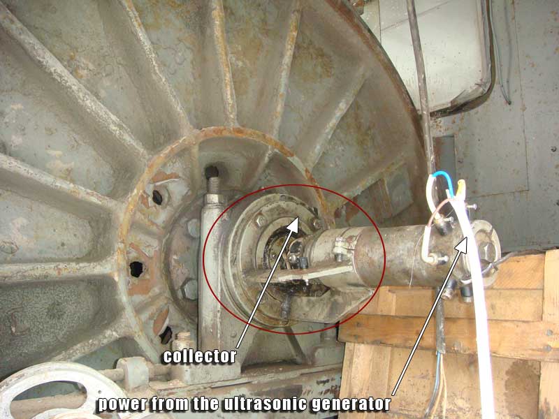
- Connecting an output cable of the generator with a collector of the geophysical lift,
Connecting power supply to the generator, switching on the equipment according to the manual.
Control of correctness of connection, control of impedance of loading and functioning of ultrasonic transducer.
Delivery of the ultrasonic equipment in the productive layer on the station.
Setting of parameters in radiation mode.
Registration of radiation parameters in working archive (input pressure, input current, mode and frequency of radiation).
Carrying out of ultrasonic stimulation under the coordinated program.
Registration of radiation parameters for each workstation.
Completion of ultrasonic stimulation.
Lifting ultrasonic transducer, control of functioning; switching-off power supply, dismantling of cables connections, preparation of the equipment for transportation.
Carrying out geophysical measurements after ultrasonic stimulation, including background thermometry in a productive zone of oil well.
End of work on an oil well.
4. Control over work of an oil well after ultrasonic stimulation.
The analysis of the geophysical measurements after the stimulation.
Estimation of power efficiency of stimulation.
Preliminary conclusion of productivity of ultrasonic stimulation for oil intensification.
Drawing up and coordination of the program of the subsequent supervision of oil well.
Recommended periodicity of measurements: once a week during the first month and once a month during the rest of the year.
Working out, registration and coordination of the report of works on the oil well.
The equipment for ultrasonic technics of a stimulation of production of oil
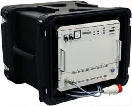
Progress-5000
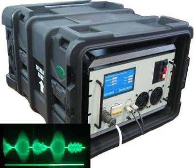 multifrequency ultrasound generator   protecting from the vibrations in the ultrasonic generator housing 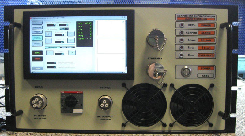
front panel of the ultrasonic generator 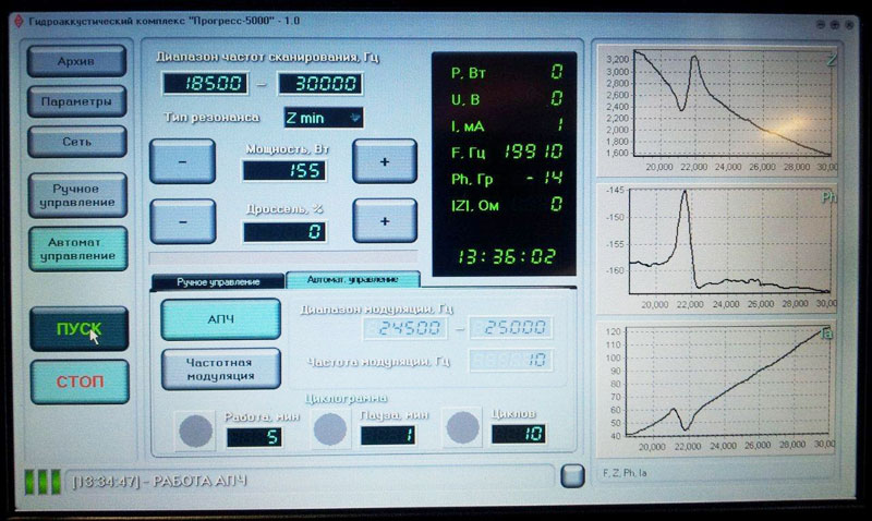 interface management program in operation  characteristics matching the generator and inverter. 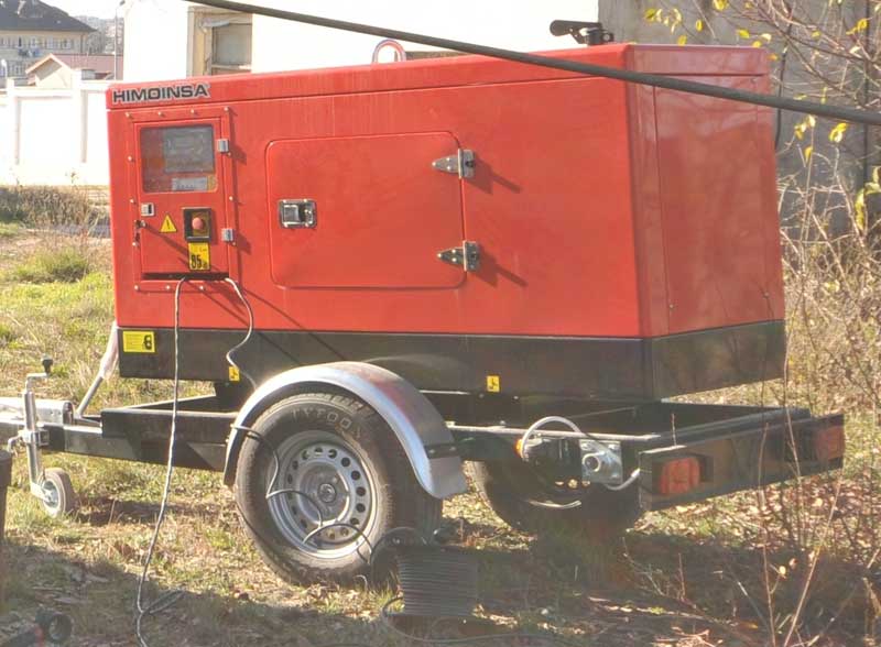 stand-alone diesel generator to power the ultrasonic generator field |
The complex works in a hand-held and self-acting regime. It is furnished by the mesomorphic display and the computer for input of operation factors and a visual verification of operation of the oscillator. The oscillator is exhausted in standard 19 "a housing in tamper modification. All plug-and-sockets and an operating controls are laied out on the front desk of the oscillator. The oscillator is advocated from breakaway of a line, short circuit in a line, no-load operation. The oscillator is furnished by input voltage stabilising. The oscillator ensures stabilising of output parametres of a current, stress and frequency. The complex is furnished by function of programmed cyclograms for operation in various requirements. The complex ensures keeping of the minutes of operations. It is envisioned self-acting archiving in a computer memory of protocols of operations after formation treatment closing of the circuit. The Oscillator is matched for operation various types of geophysical cables and ultrasonic vibrators. Emitters are designed for operation under pressure to 500 bar and temperature to +125°С.
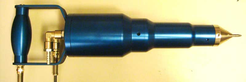
Characteristics of ultrasonic emitters:
|
||||||||||||||||||||||||||||||||||||||||||||||||||||
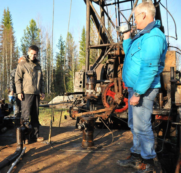
Instance of deploying of the equipment for a ultrasonic stimulation of production of oil


The result of technology

Comments:
This well is one of the first wells which was acoustically treated on 25/02/2007 for ZAO Pechoraneft Company and it is a " championess" with regard to the length of the post stimulation effect that lasts till present and is approaching 3 years ( 36 months ) now . At the same time the stable effect was attained with carbonate reservoir rock , and stimulation expenses were paid off in 5 days after stimulation ( due to sales of additionally produced oil ) . Before acoustic stimulation that well differed in sharp oil rate decrease despite the whole range of geological and technological measures taken.
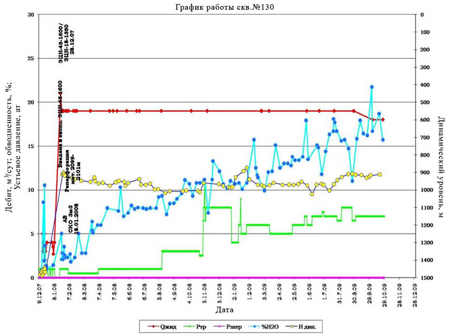
This well is the "record holder" in a series of ultrasound treatments for JSC "Pechoraneftegaz" with respect to improving flow rate indicator - 4.5 times (450%!). At the same time the well is distinguished by high stability of the work (with some increase in the percentage water content over time) with continued impressive effect for more than 2 years.
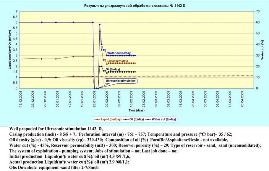
These results for the well 1142D typical series of tests in Romania at the marginal deposits are characterized by the fact that after sonication the total flow rate of fluid has not changed, but the oil production rate increased by half (1.5) times with a significant decrease in water content from 60 per cent % to 30% (2 times).
Comments:
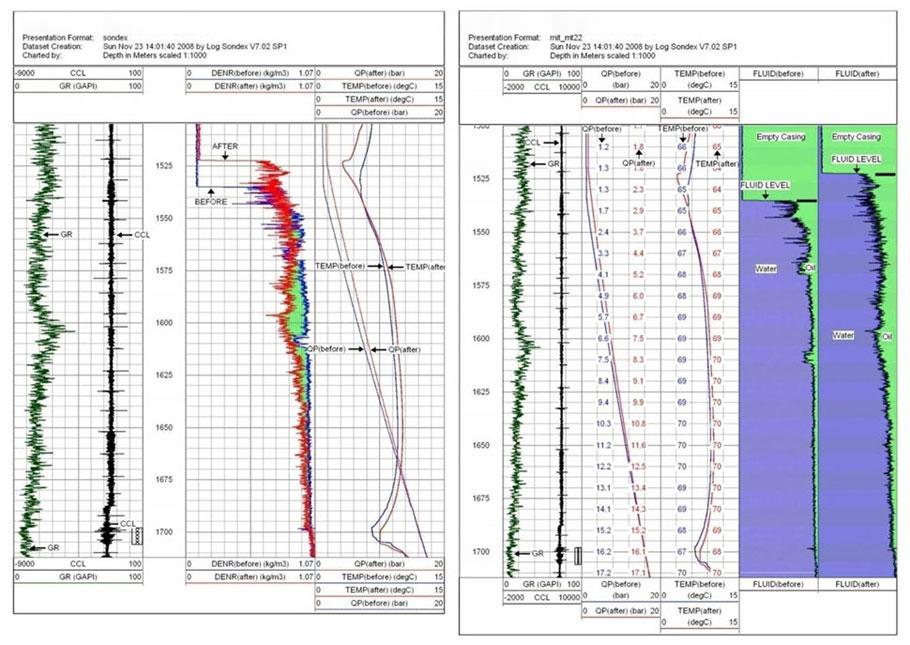
Optimization of the complex accompanying geophysical research is extremely important for financial reasons, because the cost of these studies (binding depth and assessment of the performance of the well "before" and "after" effects) are usually much higher than the actual value of the ultrasonic treatment. These are the results of research carried out by "Weatherford" (USA) accompanied by our treatments in Romania, illustrate an adequate system for the rapid assessment of the effectiveness of ultrasonic treatment and decision making. We are moving towards optimizing the set of methods and implement the technical means and technologies for various conditions, as well as their autonomy (in the assembly with our downhole ultrasonic transducers).
Information-analytical preparation of works on an oil (Questionnaire-based questionnaire)
Attention! This table is available to review in order to obtain information about the appropriateness of the work on your well need to register and fill out a similar questionnaire in the mode of on-line.
| Name of the well | |
| Well location | |
| Date of drilling / production stops Date | |
| If production is stopped - for what period or permanently | |
| Status | |
| Type of well | |
| Altitude (rotary table) | m |
| Casing length | m |
| Inner diameter of the casing | mm |
| Max angle of the well bore | degree |
| Producing reservoir | m |
| Total reservoir thickness | m |
| Effective oil saturation | m |
| Perforation intervals | a.o. m |
| Perforation intervals | |
| Perforation intervals | |
| Perforation intervals | |
| False Bottom (initial / current) | |
| Tubing length | m |
| Inner diameter of the tubing | mm |
| Oil Water contact (OWC), initial | a.o. m |
| Oil Water contact (OWC), current | a.o. m |
| Reservoir pressure, initial | atm |
| Reservoir pressure, current | |
| Bottom hole pressure, initial | |
| Bottom hole pressure, current | |
| Wellhead (buffered) pressure initial, Mpa (atm): | |
| Wellhead (buffered) pressure current, Mpa (atm): | |
| Pressure at surface (between casing / tubing - Initial) | atm |
| Pressure at surface (between casing / tubing - Current) | atm |
| Temperature of the reservoir | degree C |
| Lithology and geological index of the reservoir | |
| Porosity type | |
| Porosity | % |
| Permeability | millidarcy (mD) |
| Type of pump used | |
| Diameter of connector | mm |
| Water column, initial/current | m |
| Dynamic water column, initial/current | m |
| Liquid production, initial/current | cu m/day |
| Oil production, initial/current | cu m/day |
| Gas production, initial/current | m3/day (x1000) |
| Water production, initial/current | cu m/day |
| Water cut, initial/current | % |
| Gas factor, initial/current | % |
| Saturation pressure | atm |
| Oil density in reservoir/ at surface | g/ cu cm |
| Gas density in reservoir/at surface | g/cu cm |
| Oil viscocity in reserv./ at surf. | mPa x sec/mm2/sec |
| Parafin content | % |
| of crystallization | degree C |
| Sour gas content | % |
| Current condition of the well | in service |
| Daily well data (* attach separate file) | available |
| Borehole graphic log (*attach separate file) | |
| Additional information | |
| Estimate of well casing condition | |
| Perforator type | |
| Number of perforations | number |
| Diameter of perforation hole | mm |
| Angle of the perforation hole | degree |
| Depth of the perforation hole | mm |
| Intensification of the production: | |
| a) Treatment with HCL | cu m |
| Pressure (initial / current) | atm |
| b) Treatment with HCL | |
| Pressure (initial / current) | |
| Other Treatments | |
| Additional perforation | Multi purpose perforator Model 105C |
| Number of perforations | number |
| Diameter of perforation hole | mm |
| Angle of the perforation hole | degree |
| Depth of the perforation hole | mm |
Attention! This table is available to review in order to obtain information about the appropriateness of the work on your well need to register and fill out a similar questionnaire in the mode of on-line.
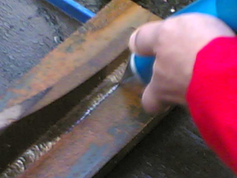
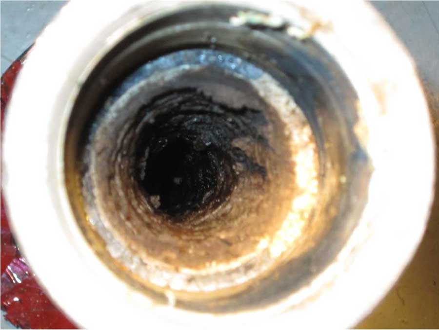
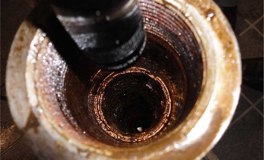
Ultrasonic Technology tube cleaning
A fragment of the pipe prior to treatment |
A fragment of the pipe after treatment |
 click to enlarge 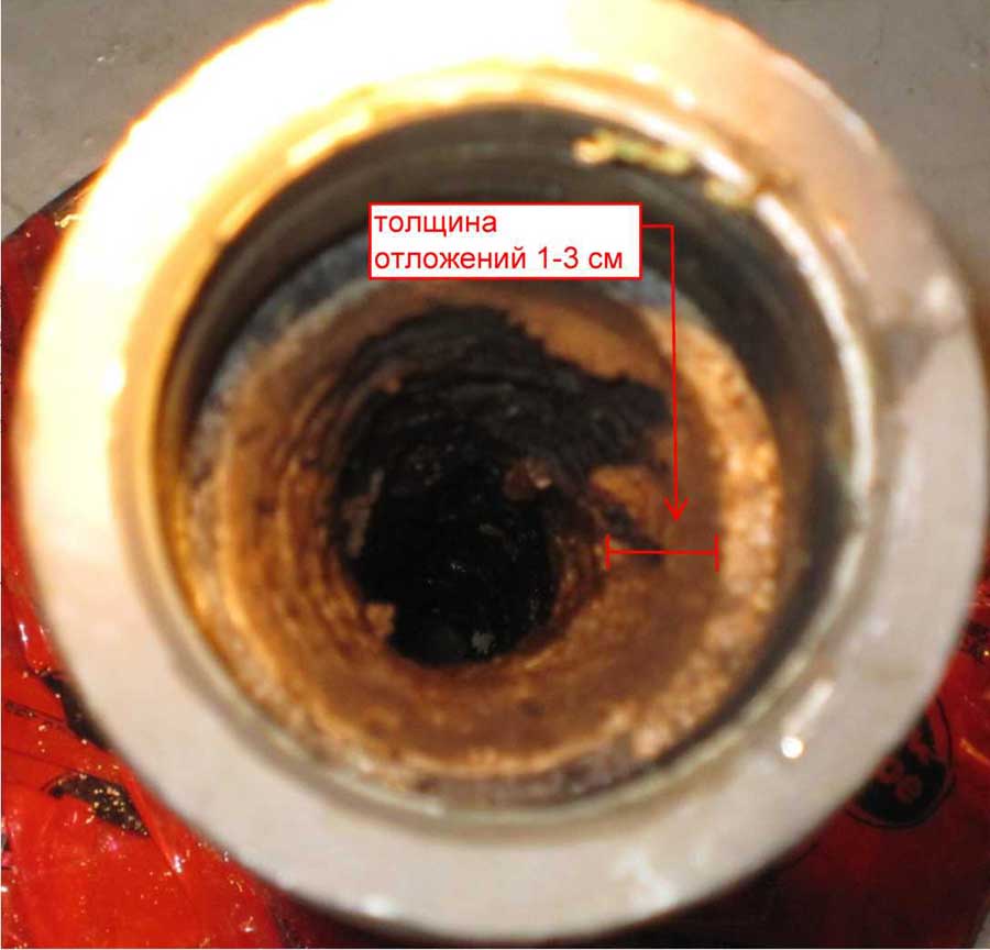 click to enlarge |
 click to enlarge 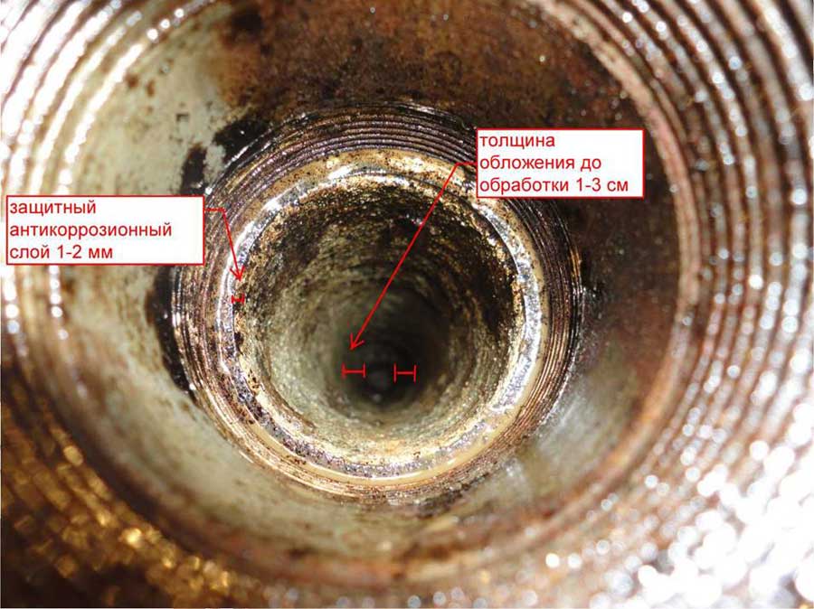 click to enlarge Ultrasonic cleaning pipes |
Experiment was carried out under stationary conditions in the laboratory «Progress Industrial Systems SA» October 12, 2011.
Complete set:
- ultrasonic instrument with centering, 2 pcs.
- clutch cable input connection and the tool-1 pc.
- machine with a winch, and pushing an ultrasonic generator, 1 pc.
- machine-tank for the collection (filtering) of dirty water, 1 pc.
- autonomous power source voltage + phase-1 pc.
- auxiliary tools and equipment, in the range
technological cycle:
- cleaned the pipe is installed at the cable entry fittings and tools In
- cleaned the tube is introduced through the coupling of ultrasonic tool Connects hose
- collect dirty water In
- tube fed a solution of contributing to ultrasonic cleaning.
- After filling the pipe section is to be cleansed Included
- ultrasonic instrument and pushing (pulling) winch.
complex features:
Power ultrasonic instrument -2500 Tues The maximum length of the site be cleaned -7000 m maximum diameter of the pipe-cleaned 250 mm. Speed cleaning tubes from 0.1 to 3 m / min
On request is possible to produce an ultrasonic tool to clean pipes up to 1500 mm.